AICHI TOKEI DENKI CO., LTD.
จำหน่าย อุปกรณ์วัด สำหรับ Liquid and Gas (Measurement for Liquid & Gas)


PRODUCTS
For Liquid Measurement
Water Meters
-
-
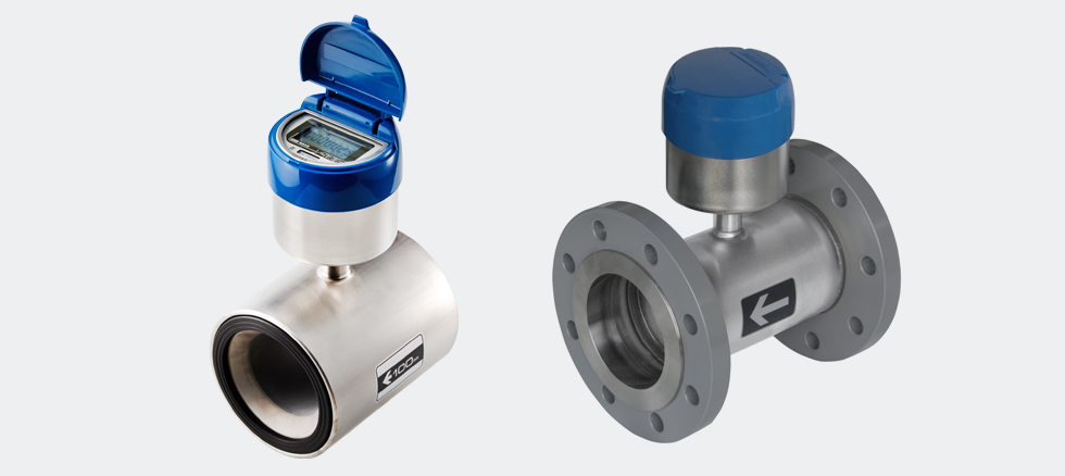
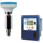
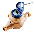
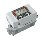
SY
- Electromagnetic Water Meters
-
Overview
Item Nominal diameter 50 75 160 300 Flow-rate range Max. flow-rate (2qp)(m3/h) 40 90 160 300 Standard flow-rate (qp)(m3/h) 20 45 80 150 Transitional flow-rate (qt)(m3/h) 4 9 16 30 Min. flow-rate (qmin)(m3/h) 0.6 1.35 2.4 4.5 Min. accurate flow-rate (qc)(m3/h) 0.04 0.09 0.16 0.3 Measurement starting flow-rate (qs)(m3/h) 0.01 0.0225 0.04 0.075 The meter does not measure a flowrate less than the measurement starting flowrate (qs).
The qs to qmin flowrate range is not within the calibration tolerance.Max. limit flow-rate (qL)(m3/h) 60 120 200 400 The 2qp to qL flowrate region is not within the calibration tolerance. Pressure drop at max. flow-rate (MPa) 0.041 0.039 0.035 0.032 Working pressure (MPa) 0.75 (Approx. 7.5kgf/cm2) Display Integrating flow (m3) 999999.9999 9999999.999 Instantaneous flow-rate (m3/h) 99.99 999.9 Meter weight (kg)10121625 10 12 16 25 Item Display No-water warning mark  ?mark lights
Low-battery alarm mark  ?mark flickers
Measurement stop alarm mark  ?mark lights
Measured
fluidSuitable working
temperature (?C)0 to +30 Fluid conductivity rate (?s/cm) 50 or more Power supply and battery life Lithium battery (Nominal 3.6V), battery life approx. 8 years (At average environmental temperature of 20?C) Environmental temperature range (?C) -10 to +55 (The battery life is shortened at higher temperature.) Waterproof structure JIS C0920 (Underwater use), continuous use at 1m water depth is possible Piping method Flange (JWWA standard) type Meter installation position Free (Horizontal, vertical and inclined installation are possible.) External
outputSY-FN type No external output functions (Only field display) SY-FC type Electronic statement signal for exclusive independent receiver (SR-4 type) Transmitter: MX35 type SY-FM type Open drain unit pulse signal Transmitter: MX39 type SY-FL type 8-bit electronic statement signal (The signal widely diffused in Japan for water and gas meters), open drain unit pulse signal Transmitter: MX38 type Accuracy

Head Loss

-
-
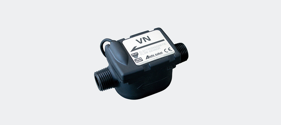
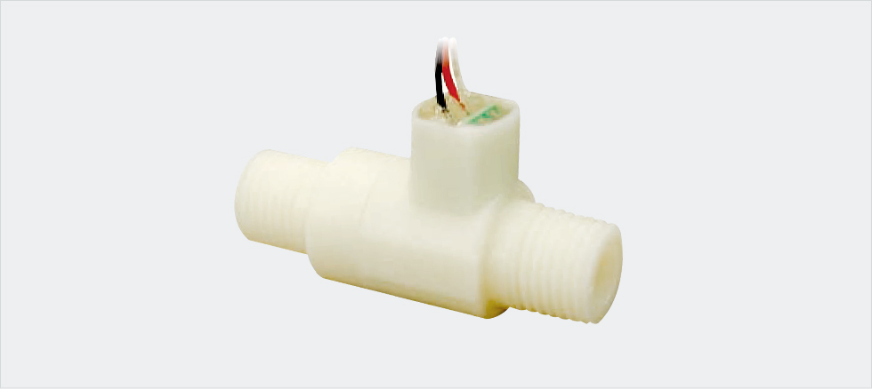
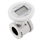
- Compact Electromagnetic Flow Sensor
-
Standard Specifications
Model VN05 VN10 VN20 Accuracy Guaranteed Flow Rate Range
(Minimum flow rate ? maximum flow rate)0.05 ? 1 L/min 0.5 ? 10 L/min 3.0 ? 60 L/min Maximum operating flow 3 L/min 25 L/min 100 L/min Low flow cut-off 0.025 L/min 0.25 L/min 1.5 L/min Accuracy
(at fluid temperature of 25?C)Frequency pulse ? 2.5 RS% (100% to 20% of maximum flow rate)
? 0.5 FS% (20% to 5% of maximum flow rate)Unit pulse ? 2.0 RS% (100% to 20% of maximum flow rate)
? 0.4 FS% (20% to 5% of maximum flow rate)Piping connection (Screw size) R1/2 R1/2 R1 Fluid temperature range 0 to 60?(Non-freezing) Fluid conductivity range 50 ?S/cm or higher Target liquids Conductive liquid that does not corrode the material exposed to it. Operating pressure 1 MPa or less Pressure loss 0.02 MPa or less Ambient temperature and humidity Temperature: -20?C to 60?C
Humidity: 35% to 85% RH (Non-condensing)Responsiveness 63% response Damping time: 2 s (Standard) Signal cables Length: 0.5 m, 4-wire
Red: Power + line
White: Output 1
Blue: Power ? line (GND)
Yellow: Output 2LED displays One LED display on the sensor body
Green: Indicates flow rate with three scales of blinking speed.
Red: Indicates abnormal state with the number of blinks.Installation position Free (Vertical piping is recommended.) Output common specifications NPN open collector
Current capacity: 20: mA or less
Voltage: 30 VDC or less
Residual voltage when ON: 1 V or lessOutput 1*2 Frequency pulse*1 Duty ratio Standard 200 Hz
(Can be configured by 0.1 Hz in the range between 20 and 400 Hz.)Unit pulse 0.001 L/P (Standard) 0.01 L/P (Standard) 0.1 L/P (Standard) Alarm*3 Can be selected from normal open (Standard) or normal close.
Alarm contents (Power supply and voltage drops/ meter failure/ empty fluid/
excessive flow rate/ excessive flow noise/ reverse flow)Switch*4 Can be selected from normal open (Standard) or normal close.
Level judgment value: Can be configured by 1% in the range of 0 ? 100%.
(The maximum flow rate is converted to 100%.)Output 2 *2 Unit pulse Same as output 1. Alarm*3 Same as output 1. Switch*4 Same as output 1. Safety Class IP X4(IP 64 compatible) Current Consumption 100mA or less Power Source Supply isolated power at 12 -24 VDC (?10%).
Use of one unit of power supply is recommended for one unit of VN.Exposed materials to fluids Body: PPS resin
Electrodes: SUS 316 L
O ring: FKM
Grounding ring: SUS 316* 1: The frequency at maximum flow rate
* 2: The set value of Output 1 and 2 and options are the factory-default settings. The set value cannot be changed after installation.
* 3: The alarm can only be selected for either Output 1 or 2.
* 4: The window judgment uses Output 1 and 2.
(Note) Not complied with the lightning surge protection in CE.
-
-
VNS
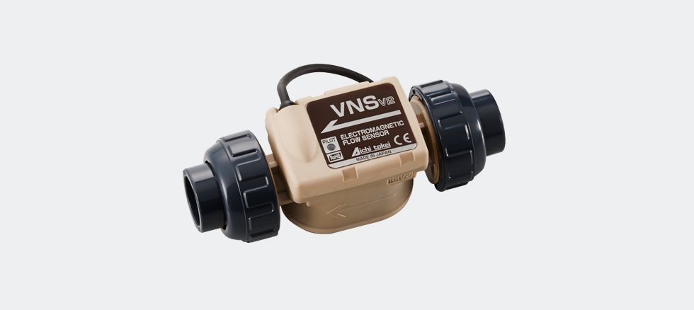
- Compact Electromagnetic Flow Sensors
-
Specifications
Principal of measurement Electromagnetic type with Faraday?s law of electromagnetic induction Model (PROVISIONAL) VNS05 VNS10 VNS20 Accuracy assured flow-rate range *2 0.05?1 L/min 0.5?10 L/min 3.0?60L/min Measurement starting flow-rate 0.025 L/min 0.25 L/min 1.5 L/min Piping connection Socket type
union joint (16A)Socket type
union joint (16A)Socket type
union joint (20A)Accuracy *3 Unit pulse output ?2.0%RS (100~20% of the maximum flow-rate)
?0.4%FS (20~5% of the maximum flow-rate)Response time (at 63% response) Standard: 2 seconds. Setting within the range of 0.1600 seconds is available. Fluid temperature range 0~40?C, freezing must be avoided. (VNS05 can resist 15 minutes per day of 95?C, whereas its accuracy is out of guarantee. Measurable fluid - Sodium hypochlorite (Concentration of 1~12%)
- Sodium hydroxide aqueous solution (Concentration of 10~25%)
For other kind of liquid, by selecting with reference to the following major materials of the fluid-touching materials, please consult with us for suitability confirmation.
Working ambient temperature range -20~60?C Ambient temperature range for storage -20~70?C Fluid pressure range 0~1MPa Signal cable - Standard cable length 0.5m
- 4-wires (AWG26)
Line 1: Power + line
Line 2: Power ? line
Line 3: Output 1
Line 4: Output 2 - Top of the each: Soldered stranded wire
Display 1 LED display at the flowsensor?s body - Green: Flow-rate indication (Indication with blinking speed of 3 steps)
- Red: Alarm indication (Indication of abnormality with numbers of blinking)
Place of installation Indoor installation
(In case of outdoor installation, please take necessary measure so that the flowsensor is not exposed to rain and sun beam directly.)Enclosure IPX4 Corresponding standard CE Standard *1 Fluid-touching materials Main body: PEEK resin
Electrodes: Pure titanium (2 kinds)O-ring: For sodium hypochlorite, etc. ? FKM (Fluoro rubber)
For Sodium hydroxide aqueous solution, etc. ? EPDM (Ethylene propylene rubber)Installation position Free (Vertical piping is recommended.) *1 Except EN61000-4-5(surge) because VN series is intended to utilize as the built-in flowsensor of a machine,etc.
*2 (Minimum flow-rate ~ maximum flow-rate)
*3 For constant flow without pulsation.
-
-
-
OF-Z
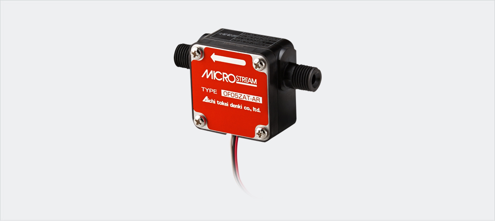
- Microflow Sensor
-
Specifications
Standard specifications
Model OF05ZAT OF10ZAT OF05ZZT OF10ZZT Flow rate range Liquid viscosity0.3 ? 0.8mPa?s 0.085 ? 0.85L/min 0.7 ? 5L/min 0.085 ? 0.85L/min 0.7 ? 5L/min Liquid viscosity0.8 ? 2.0mPa?s 0.05 ? 0.85L/min 0.35 ? 5L/min 0.05 ? 0.85L/min 0.35 ? 5L/min Liquid viscosity2.0 ? 5.0mPa?s 0.017 ? 0.85L/min 0.17 ? 5L/min 0.017 ? 0.85L/min 0.17 ? 5L/min Liquid viscosity5.0 ? 200mPa?s 0.085 ? 0.85L/min 0.085 ? 5L/min 0.085 ? 0.85L/min 0.085 ? 5L/min Accuracy ?2%RS(In the standard installation position) Measurable liquid Types of measurable liquid Please decide based on the major materials exposed to the fluid, which are described below. Major measurable liquid Cold and hot water and heating, light and heavy oil Mildly acidic and mildly alkaline liquid Maximum operating pressure 0.5MPa(When the liquid is at 20?C). Pressure loss 4 kPa or less 10 kPa or less 4 kPa or less 10 kPa or less Fluid temperature range -10 to +70?(No condensing) Responsiveness -10 to +70? 35?85%RH(No condensing) Output signal Voltage pulse output Voltage pulse 3-wireLength of wire: Approx. 480 mmVoltage pulse duty ratio 2/8 < A/B < 8/2When voltage is applied at 12 VDC or less,High: 10 VDC or moreLow: 1 VDC or less 
Open collector output Open collector pulse (Capacity: 6 mA DC or less)Length of 4 lead wire: Approx. 600 mm Pulse constant 0.46mL/P 2.5mL/P 0.46mL/P 2.5mL/P Maximum frequency Approx. 30Hz Approx. 33Hz Approx. 30Hz Approx. 33Hz Minimum pulse width Approx. 0.0065s Approx. 0.006s Approx. 0.0065s Approx. 0.006s Applied voltage range 3 ? 24VDC *1 Power consumption 0.2VA or less Structure Splash-proof structure (IP64 compatible) for indoor use Connection R1 / 4 R1 / 2 R1 / 4 R1 / 2 Mass Approx. 100 g Approx. 140 g Approx. 100 g Approx. 140 g Major materials of the part exposed to liquid Case PPS Rotor PPS O-ring NBR FKM Shaft SUS304 SiC ? If the fluid might contain fine particles, please install the filter with a #80 mesh screen or higher before the flow sensor.
? Do not measure gasoline, sodium hydroxide (caustic soda), oxygenated water (Oxydol) and acidum hydrochloricum (strong acid fluid).
*1. Apply the same voltage to the sensor power supply (red ? black) and pulse output (blue and white ? black).
(Applicable only for open collector output)
-
-
-
OF-WN/OF-WP
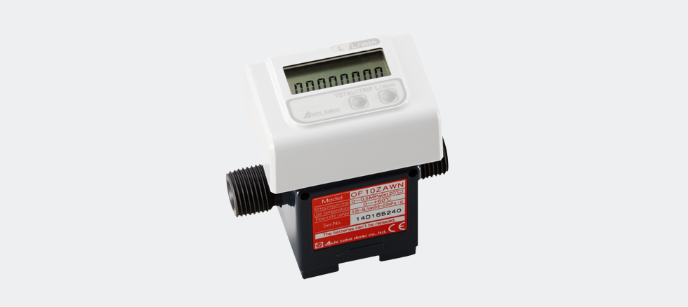
- Microstream Sensor
-
Spec
Instantaneous flow-rateIntegrating flow volume
flowmeter OF-WN TypeOF05ZAWN OF10ZAWN Instantaneous flow-rateIntegrating flow volume
flowmeter (with pulse output)
OF-WP TypeOF05ZAWP OF10ZAWP Flow-rate
range (m3/h)Fluid viscosity
0.3 ? 0.8mPa?S0.085 ? 0.85L/min 0.7 ? 5L/min 0.8 ? 2.0mPa?S 0.05 ? 0.85L/min 0.35 ? 5L/min 2.0 ? 5.0mPa?S 0.017 ? 0.85L/min 0.17 ? 5L/min 5.0 ? 200mPa?S 0.0085 ? 0.85L/min 0.085 ? 5L/min Accuracy
(*1)Flow-rate indication ?2%RS?0.007L/min ?2% RS?0.04L/min Volume indication ?2%RS Measurable
fluidsVarious liquids Please select with reference to the following major materials
of the liquid-touching materialsMajor fluids Water, hot water, kerosene, heavy oil Max. working pressure 0.5MPa (at the time of fluid temperature of 20?C) Pressure drop Not more than 4kPa Not more than 10kPa Fluid temperature range 0 to +60?C Output signal (for OF-WP) Open drain output (Equivalent to open collector)
Pulse width: Not less than 5ms
Max. rating voltage: 30 VDC
Output capacity: ?ON resistance? Not more than 150?,
?OFFresistance? Not less than 100k? (Remained voltage
not more than 1.5V in case of input current not more than 10mA)Pulse unit (for OF-WP) 10mL/p Ambient temperature range 0 to +60?C 35 to 85%RH
(Dew condensation must be avoided)LCD Flow-rate Smallest Scale 0.007L/min 0.04L/min Display digits 0.000L/min 00.00L/min Volume Smallest Scale 0.001L 0.01L Display digits 00000.000L 000000.00L Power supply Built-in lithium battery (Battery life 4 years. Not replaceable.) Structure IP64 equivalent, Indoor installation Connection R1/4 R1/2 Meter Weight Approx. 240g Approx. 260g Major materials
of the liquid
touching partsCasing PPS Rotor PPS O-ring NBR Pivot SUS304 Instantaneous flow-rate
Integrating flow volume
flowmeter OF-WN TypeOF05ZZWN OF10ZZWN Instantaneous flow-rate
Integrating flow volume
flowmeter (with pulse output)
OF-WP TypeOF05ZZWP OF10ZZWP Flow-rate
range (m3/h)Fluid viscosity
0.3 ? 0.8mPa?S0.085 ? 0.85L/min 0.7 ? 5L/min 0.8 ? 2.0mPa?S 0.05 ? 0.85L/min 0.35 ? 5L/min 2.0 ? 5.0mPa?S 0.017 ? 0.85L/min 0.17 ? 5L/min 5.0 ? 200mPa?S 0.0085 ? 0.85L/min 0.085 ? 5L/min Accuracy
(*1)Flow-rate indication ?2%RS?0.007L/min ?2% RS?0.04L/min Volume indication ?2%RS Measurable
fluidsVarious liquids Please select with reference to the following major materials
of the liquid-touching materialsMajor fluids Water, hot water, kerosene, heavy oil Max. working pressure 0.5MPa (at the time of fluid temperature of 20?C) Pressure drop Not more than 4kPa Not more than 10kPa Fluid temperature range 0 to +60?C Output signal (for OF-WP) Open drain output (Equivalent to open collector)
Pulse width: Not less than 5ms
Max. rating voltage: 30 VDC
Output capacity: ?ON resistance? Not more than 150?,
?OFFresistance? Not less than 100k? (Remained voltage
not more than 1.5V in case of input current not more than 10mA)Pulse unit (for OF-WP) 10mL/p Ambient temperature range 0 to +60?C 35 to 85%RH
(Dew condensation must be avoided)LCD Flow-rate Smallest Scale 0.007L/min 0.04L/min Display digits 0.000L/min 00.00L/min Volume Smallest Scale 0.001L 0.01L Display digits 00000.000L 000000.00L Power supply Built-in lithium battery (Battery life 4 years. Not replaceable.) Structure IP64 equivalent, Indoor installation Connection R1/4 R1/2 Meter Weight Approx. 240g Approx. 260g Major materials
of the liquid
touching partsCasing PPS Rotor PPS O-ring FKM Pivot SiC In case there is possibility that any particle is flown in the liquid to be measured, please install a filter of not less than 80 meshes at the inlet side of the flowmeter.
Gasoline, Sodium hydroxide (Caustic soda), Hydrogen peroxide solution (Oxydol), and Hydrochloric acid are not applicable.
*1: With the standard installation position.
-
-
-
ND
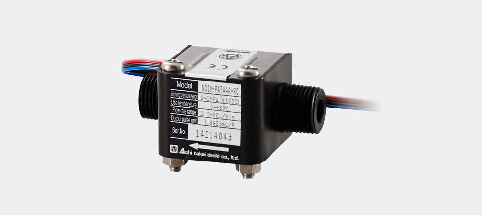
- Flow Sensor
-
Standard specifications (ND05-NATAAC – ND10-NATAAA)
Model ND05-N
ATAAOND05-P
ATAAOND05-T
ATAAAND10-N
ATAAAFlow rate range 0.3 ? 3.0 L/min 1.5 ? 20 L/min Accuracy ?2%RS (In the standard installation position) Measurable liquid Types of measurable liquid (Please decide based on the major materials exposed to fluid, which are described below.) Maximum operating pressure 1MPa (When the liquid is at 20?C) Pressure loss 12 kPa or less
(at 3 L/min)20 kPa or less
(at 20 L/min)Range of liquid viscosity 0.5 ? 1.5 mPa?s (Water equivalent) Fluid temperature range 0 to + 70? 0 to + 60? 0 to + 70? Responsiveness -10 to +70? 35 to 85%RH (No condensing) Output signal Open collector pulse, 4-wire
Length of wire: Approx. 600 mmDuty ratio 3/7 < A/B < 7/3
Pulse constant 2.5 mL/P 7.69 mL/P Maximum frequency 20Hz Approx. 44Hz Minimum pulse width 0.015s Approx. 0.007s Applied voltage range 3 ? 24VDD Power consumption 0.2 VA or less Structure Splash-proof structure (IP64 compatible) for indoor use Connection R1/2 Mass Approx. 150g Approx. 120g Major materials of the part
exposed to liquidCase Denatured PPO PP ETFE Denatured PPO Impellers POM ETFE POM Pivot SUS304 PA ETFE SUS304 O-ring NBR FKM NBR Magnet Sa-Co * Ba-Fe Standard specifications (ND10-PATAAA – ND20-PATAAA)
Model ND10-P
ATAAAND10-T
ATAAAND20-N
ATAAAND20-P
ATAAAFlow rate range 1.5 ? 20 L/min 1.0 ? 10 L/min 3.0 ? 60 L/min Accuracy ?2%RS (In the standard installation position) Measurable liquid Types of measurable liquid (Please decide based on the major materials exposed to fluid, which are described below.) Maximum operating pressure 1MPa (When the liquid is at 20?C) Pressure loss 20 kPa or less
(at 20 L/min)15 kPa or less
(at 10 L/min)60 kPa or less
(at 60 L/min)Range of liquid viscosity 0.5 ? 1.5 mPa?s (Water equivalent) Fluid temperature range 0 to + 60? 0 to + 70? 0 to + 60? Responsiveness -10 to +70? 35?85%RH (No condensing) Output signal Open collector pulse, 4-wire
Length of wire: Approx. 600 mmDuty ratio 3/7 < A/B < 7/3Pulse constant 7.59 mL/P 25 mL/P Maximum frequency Approx.44Hz Approx.22Hz 40Hz Minimum pulse width Approx.0.007s Approx.0.014s 0.0075s Applied voltage range 3 ? 24VDD Power consumption 0.2 VA or less Structure Splash-proof structure (IP64 compatible) for indoor use Connection R1/2 R3/4 Mass Approx. 120g Approx. 360g Major materials of the part
exposed to liquidCase PP ETFE Denatured PPO PP Impellers POM ETFE POM Pivot PA ETFE SUS304 O-ring FKM NBR FKM Magnet Ba-Fe Sm-Co * Ba-Fe ? ND05-TATAAA and ND10-TATAAA should only be installed in the standard installation position.
*1. Apply the same voltage to the sensor power supply (red ? black) and pulse output (blue and white ? black).*2. This magnet is not exposed to liquid.
-
-
-
NW/NW-P
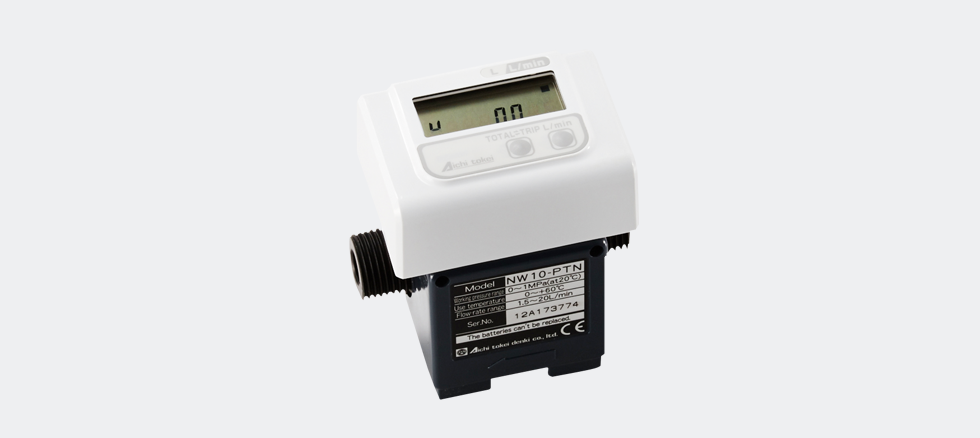
- Instantaneous Flow-rate/
Integrating Flow Volume Flowmeter -
Specifications
Instantaneous flow-rate?
Integrating flow volume
flowmeter NW TypeNW05-NTN NW05-PTN NW05-TTN NW10-NTN Instantaneous flow-rate?
Integrating flow volume
flowmeter (with pulse output)
NW-P TypeNW05-NTP NW05-PTP NW05-TTP NW10-NTP Flow-rate range (m3/h) 0.3 ? 3L/min 1.5 ? 20L/min Accuracy Flow-rate indication ?2%RS?0.05L/min ?2%
RS?0.2L/minVolume indication ?2%RS (with the standard installation position) Measurable fluids Various liquids (Please select with reference to
the following major materials of the liquid-touching materials)Max. Working Pressure 1MPa (at the time of fluid temperature of 20?C) Pressure Drop Not more than 12kPa
(At the time of 3L/min)Not more than
20kPa
(At the time of
20L/min)Fluid viscosity range 0.5-1.5mPa?s Fluid temperature range 0?60?C Ambient temperature range 0?60?C 35-85%RH(Dew condensation must be avoided) Output signal (for NW-P) Open drain output (Equivalent to open collector)
Pulse width: Not less than 5ms
Max. rating voltage: 30 VDC
Output capacity: ?ON resistance? Not more than 150?,
?OFFresistance? Not less than 100k? (Remained voltage
not morethan 1.5V in case of input current not more than 10mA)Pulse unit (for NW-P) 10mL/p 1L/p LCD Flow-rate Smallest Scale 0.05L/min 0.2L/min Display digits 00.00L/min 000.0L/min Volume Display digits 000000.00L 0000000.0L Power supply Built-in lithium battery (Battery life 4 years. Not replaceable.) Measurable fluids Refer to ?MEASURABLE FLUID AND PARTS MATERIALS? Structure IP64 equivalent, Indoor installation Connection R1/2 Meter Weight Approx. 280g Approx. 250g Major materials
of the liquid
touching partsCasing Denatured
PPOPP ETFE Denatured
PPOVane wheel POM ETFE POM Pivot SUS304 PA ETFE SUS304 O-ring NBR FKM NBR Magnet Sa-Co *1 Ba-Fe Instantaneous flow-rate?
Integrating flow volume
flowmeter NW TypeNW10-PTN NW10-TTN NW20-NTN NW20-PTN Instantaneous flow-rate?
Integrating flow volume
flowmeter (with pulse output)
NW-P TypeNW10-PTP NW10-TTP NW20-NTP NW20-PTP Flow-rate range (m3/h) 1.5-20L/min 1.0-10L/min 3.0-60L/min Accuracy Flow-rate indication ?2%RS?0.2L/min ?2% RS?0.5L/min Volume indication ?2%RS (with the standard installation position) Measurable fluids Various liquids (Please select with reference to
the following major materials of the liquid-touching materials)Max. Working Pressure 1MPa (at the time of fluid temperature of 20?C) Pressure Drop Not more than
20kPa
(At the time of
20L/min)Not more than
15kPa
(At the time of
10L/min)Not more than 60kPa
(At the time of 60L/min)Fluid viscosity range 0.5-1.5mPa?s Fluid temperature range 0?60?C Ambient temperature range 0?60?C 35-85%RH(Dew condensation must be avoided) Output signal (for NW-P) Open drain output (Equivalent to open collector)
Pulse width: Not less than 5ms
Max. rating voltage: 30 VDC
Output capacity: ?ON resistance? Not more than 150?,
?OFF resistance? Not less than 100k? (Remained voltage
not more than 1.5V in case of input current not more than 10mA)Pulse unit (for NW-P) 1L/p LCD Flow-rate Smallest Scale 0.2L/min 0.5L/min Display digits 000.0L/min Volume Display digits 0000000.0L Power supply Built-in lithium battery (Battery life 4 years. Not replaceable.) Measurable fluids Refer to ?MEASURABLE FLUID AND PARTS MATERIALS? Structure IP64 equivalent, Indoor installation Connection R1/2 R3/4 Meter Weight Approx. 250g Approx. 500g Major materials
of the liquid
touching partsCasing PP ETFE Denatured
PPOPP Vane wheel POM ETFE POM Pivot SUS304 ETFE SUS304 O-ring FKM NBR FKM Magnet Ba-Fe Sa-Co *1 Ba-Fe Any installation position other than the standard installation position is not available for NW05-TTN, NW05-TTP, NW10-TTN, and NW10-TTP.
*1: The magnet does not touch liquid.
-
-
-
NDV10
- Small-size Flowsensor
-
-
-
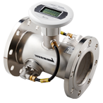
TRA
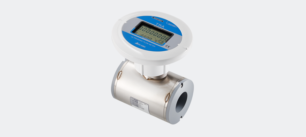
- Ultrasonic Flow Meter for Liquid
-
Spec
Model TRL40T TRL50T TRL80T TRL100T Size mm 40A 0A 80A 100A in. 1 1/2 2 3 4 Measurable fluids Drinking water, processing water, industrial water, pure water, etc. Max.pressure NPa 1 Bar(PSI) 10 (145) Flow range m3/h 0.6 to 30 1 to 50 2 to 100 4 to 200 US gal/min 2.64 to 132 4.4 to 220 8.8 to 440 17.6 to 880 Accuracy ?2% of rate m3/h 3 to 30 5 to 50 10 to 100 20 to 200 US gal/min 13.2 to 132 22 to 220 44 to 440 88 to 880 ?5% of rate m3/h 0.6 to 3 1 to 5 2 to 10 4 to 20 US gal/min 2.64 to 13.2 4.4 to 22 8.8 to 44 17.6 to 880 Fluid temperature range 0 to 50?C (32?F to 122?F) Display Main Cyclic display : Total integrated flow/Trip integrated flow Integrated flow LCD 10digit Sub Instantaneous flow Cyclic display : Instantaneous/Temperature Temperature LCD 4digit Output Pulse Pulse per 0.1m3 or Pulse per 10 USgals (open drain unit pulse) Analog 4 to 20mA (for DC power only) Power supply Battery Lithium battery with a life of 10 years (replaceable) Extermal 24V DC Connection Wafer Installation position Free Materials in contact with fluid PVC Protection class IP64 Weight 1.4kg (3.1lbs) 1.7kg (3.7lbs) 2.4kg (2.4lbs) 3.1kg (3.1lbs)
-
-
-
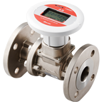
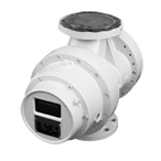
AGV
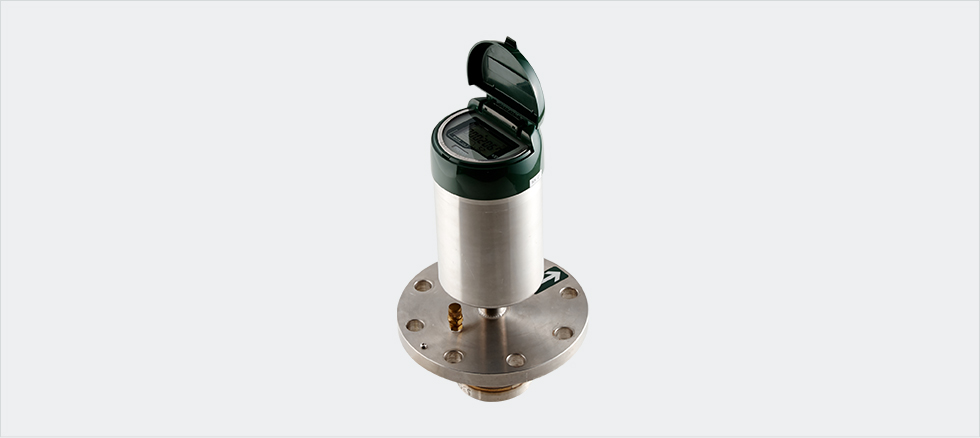
- Electromagnetic Flow Meters
for Agricultural Applications -
Specifications
Standard specifications (Diameter 200 ? 350 mm)
Diameter (mm) 200 250 300 350 Measurement range *1 Flow velocity 0.1 ? 5m/s Maximum flow rate Qmax (L/s) 170 254 375 459 Accurate lower flow rate Qc (L/s) 3.4 5.3 7.5 9.4 Accumulated accuracy (%) ?Diameter 200 ? 350 mm 
Operating pressure 2 MPa (Flange type: 1 MPa, Saddle type: 0.5 MPa) Test pressure 4 MPa (Flange type: 2 MPa, Saddle type: 1 MPa) Fluid temperature range 0 to +40? Environment temperature range -10 to +50? Minimum conductivity 50 ?S/cm * 50 ?S/cm or more for normal tap water Display * 2 Integrated flow rate (unit L), Instantaneous flow rate (unit L/s), Empty fluid indication, Battery voltage drop indication Power source Built-in lithium battery, Battery life: about 20 years (Under an environmental temperature of 20?C) Piping method Sensor installation part: Flange type: Use existing measuring pipes (Dedicated flange adaptor or dedicated saddle)
Measuring short piping: Both sides/one side flanges (Clean water/JIS10K/JIS20K)External output *3 (1) No output No output (2) Code output *4 SS format code output, accumulated and instantaneous flow rate (transmitted every 1.8 seconds). (3) Pulse output Open drain pulse output
Pulse ON time: 100?10 ms
Pulse unit: 100 L /P, 1 m3/P, (10 m3/P)
Maximum load: 30 VDC, 20 mA(4) 8-bit telegram output 2-wire: 8-bit telegram output
4-wire: 8-bit electronic output + Open drain pulse output (The same specifications as the above pulse output)Waterproof structure IP 68 (Can be used continuously under water.) Standard specifications (Diameter 400 ? 800 mm)
Diameter (mm) 400 450 500 500 700 800 Measurement range *1 Flow velocity 0.1 ? Sm/s Maximum flow rate Qmax
(L/s)617 785 970 1398 1898 2493 Accurate lower flow rate Qc
(L/s)12.3 15.7 19.4 28.0 38.0 49.9 Accumulated accuracy (%) ?Diameters400 ? 800mm 
Operating pressure 2 MPa (Flange type: 1 MPa, Saddle type: 0.5 MPa) Test pressure 4 MPa (Flange type: 2 MPa, Saddle type: 1 MPa) Fluid temperature range 0 to +40? Environment temperature range -10 to +50? Minimum conductivity 50 ?S/cm *50 ?S/cm or more for normal tap water Display * 2 Integrated flow rate (unit L), Instantaneous flow rate (unit L/s), Empty fluid indication, Battery voltage drop indication Power source Built-in lithium battery, Battery life: about 20 years (Under an environmental temperature of 20?C) Piping method Sensor installation part: Flange type: Use existing measuring pipes
(Dedicated flange adaptor or dedicated saddle)
Measuring short piping: Both sides/one side flanges (Clean water/JIS10K/JIS20K)External output *3 (1) No output No output (2) Code output *4 SS format code output, accumulated and instantaneous flow rate (transmitted every 1.8 seconds). (3) Pulse output Open drain pulse output
Pulse ON time: 100?10 ms
Pulse unit: 100 L/P, 1 m3/P, (10 m3/P)
Maximum load: 30 VDC, 20 mA(4) 8-bit telegram output 2-wire: 8-bit telegram output
4-wire: 8-bit electronic output + Open drain unit pulse output (The same specifications as the above pulse output)Waterproof structure IP 68 (Can be used continuously under water.) Avoid using the meter in such a corrosive gas environment as chlorine and hydrogen sulfide.
Please contact us if you want to measure fluid other than water.
*1. The flow rate is calculated at ?Sch 10S.?
*2. Consider the instantaneous flow rate as a reference.
*3. For the output unit, code output unit, pulse output (with a built-in lithium battery with 10 years lifespan under an average environmental temperature of 20?C)
and 8-bit telegram communication (with a built-in lithium battery with 8 years lifespan under an average environmental temperature of 20?C) are available, and
it comes with cables. The external output can only be changed by replacing the output unit.
*4. A dedicated receiver is available.
-
-
-
RF
- Flow Rate Sensor For River
-
-
-
E-moni
- Insertable Electromagneteic Meter
-
-
-
DSV
- Disposable Electromagnetic Flowsensors
-
-
-
FG
- Electromagnetic Flow Meter
for Non-Full Water
-
-
-
CX
- Capacitive Electromagnetic Flowsensor
-
-
-
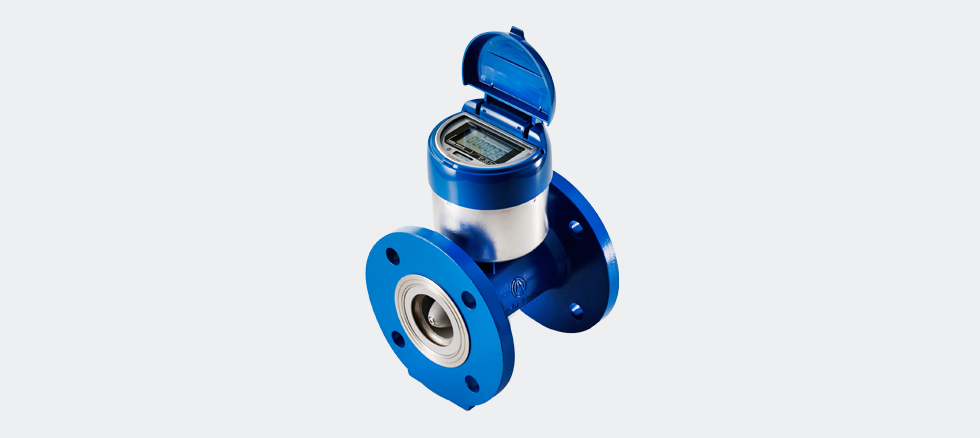
Electronics Water Meter
- E-Series
-
For Liquid Measurement
-
-
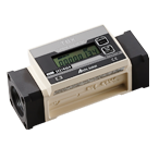
TRX/TRZ
- Ultrasonic Flow Meters for Air
(RS485 Output Specifications)
-
-
TRX

- Ultrasonic Flow Meters for Air
(Diameters 40A, 50A, 65A, and 80A)
-
-
TRZ
- Ultrasonic Flow Meters for Air
(Diameters 100A, 150A and 200A)
-
-
-
AS
- Ultrasonic Flow Meters for Fuel Gas
-
-
-
TBX/TBZ
- Turbine Gas Meters
for Flow Management
-
-
-
Governor
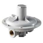
- Pressure-reducing valve series
-
-
-
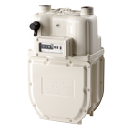
Roots
- Gas Meter R Series
-
-
-
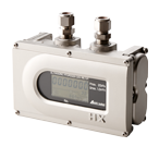
UX
- High Performance Ultrasonic Flow Meters for Fuel Gas
-
-
-
NB
- Intelligent Gas Meter
-
-
-
HX
- Taking up challenges in new measurement
-
-
-
MP-401
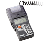
- Digital Manometer
for Town Gas and LP Gas
-
Credit:?http://www.aichitokei.co.jp/,?https://www.aichitokei.net